Linux
DIY Linux Router - Part 2 - Network and Internet
This is the second part of a multi-part series describing how to build your own Linux router.
- Part 1: Initial Setup
- Part 3: Users, Security and Firewall
- Part 4: Podman and Unbound
- Part 5: Wifi
- Part 6: Nextcloud and Jellyfin
- Part 7: File Sharing
- Part 8: Backup
- Impermanence Storage
In the first part, we covered the hardware setup and installed a basic Linux system using NixOS on top of a ZFS filesystem.
In this part, we will configure VLANs and their networks, set up a PPPoE connection, configure the DHCP server, and implement basic firewall rules.
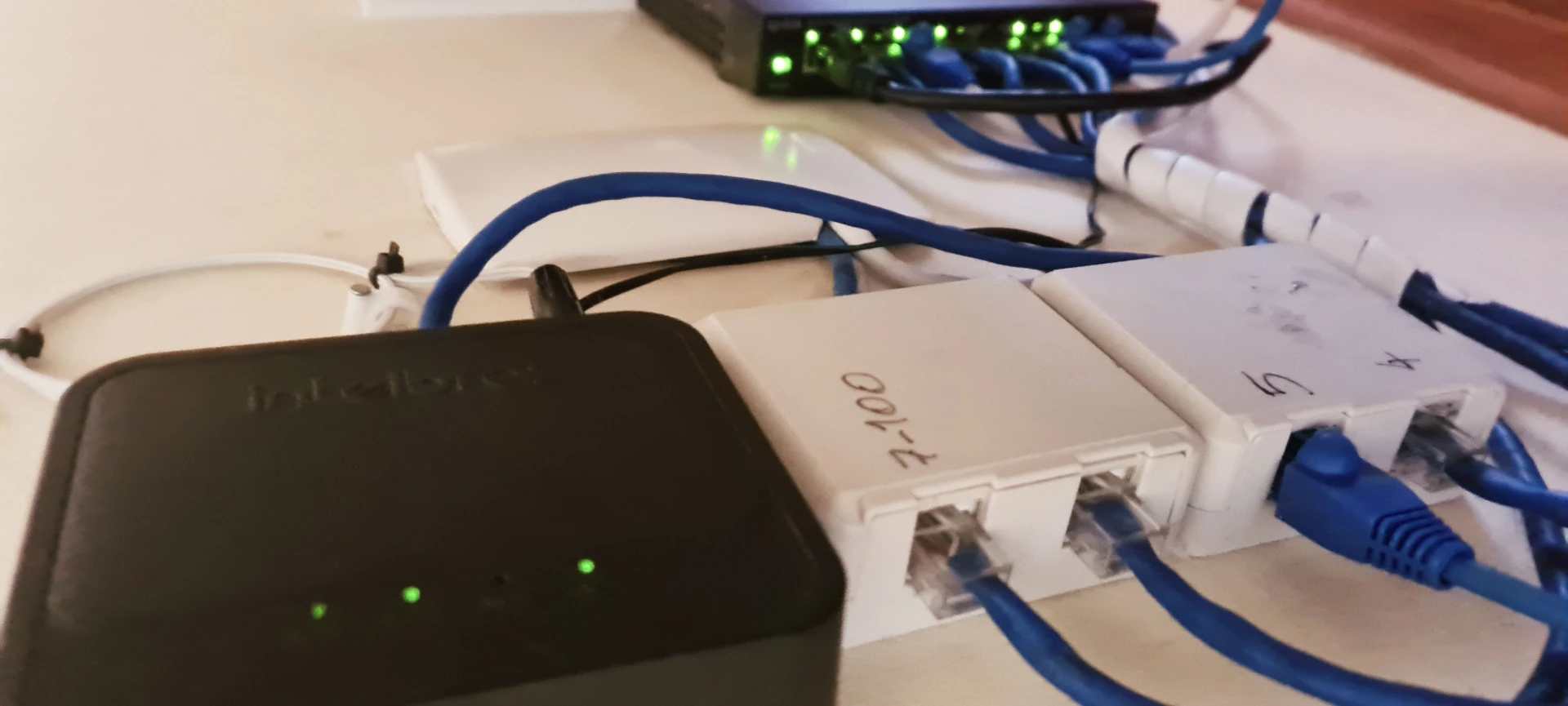
Table of Contents
VLANs
In this setup, I am using the TP-Link TL-SG108E managed switch to take advantage of its VLAN capabilities.
The OSI Model
The OSI model defines a network's communication architecture across seven layers:
- Layer 1: Physical Layer – Handles physical connections like cables, NICs, and connectors.
- Layer 2: Data Link Layer – Manages MAC addresses, bridges, switches, and VLANs.
- Layer 3: Network Layer – Responsible for IP addressing and routing.
- Layer 4: Transport Layer – Facilitates data transport using protocols like TCP and UDP.
- Layer 5: Session Layer – Manages connections between client and server applications.
- Layer 6: Presentation Layer – Handles data formatting and encoding.
- Layer 7: Application Layer – Provides end-user applications with access to the network.
You can learn more about the OSI model here.
What Is a VLAN?
A VLAN (Virtual Local Area Network) segments a network logically rather than physically. Without VLANs, network segmentation would require separate switches and network interfaces. This method is referred to as Layer 1 segmentation, while VLAN-based segmentation operates at Layer 2.
In Layer 2, data is transported in frames, each containing a frame header and frame data. The frame header includes key information such as the target MAC address and, optionally, a VLAN tag. A VLAN tag ensures that data frames are delivered to their intended network segment, as configured on a smart switch.
VLANs isolate traffic between different segments, ensuring that devices in one VLAN cannot directly communicate with those in another. To use VLANs effectively, follow these principles:
- Each VLAN is identified by a PVID (Port VLAN ID).
- Ports can be configured to accept traffic from multiple tagged VLANs.
- Untagged traffic on a port is assigned to its default VLAN, typically PVID 1.
Untagged VLANs
An untagged VLAN divides a switch into isolated segments. For instance, assigning:
- Ports 1-4 to PVID 1
- Ports 5-8 to PVID 2
will create two separate networks where devices connected to Ports 1-4 cannot communicate with those on Ports 5-8.
Tagged VLANs
Tagged VLANs allow a single port to handle traffic from multiple VLANs. The switch examines the VLAN tag in the frame header to route traffic appropriately. This is similar to connecting multiple network adapters to different switches but using a single physical interface.
For example:
- Ports 1 and 3 are tagged for VLAN 30 and VLAN 90.
- Traffic tagged as VLAN 30 or VLAN 90 from Port 1 will only reach Port 3, and vice versa.
Devices connected to tagged ports must be configured to recognize VLAN tags; otherwise, the traffic will be discarded.
Hybrid Configuration (Tagged and Untagged)
A smart switch can strip VLAN tags from frames before forwarding them to a port. For example:
- Port 1 is tagged for VLAN 2.
- Port 2 is assigned to PVID 2 as untagged.
Traffic sent from Port 1 tagged as VLAN 2 will be delivered to Port 2 as untagged. This is useful for scenarios where a device, such as an ISP modem, does not support VLAN tagging.
Advantages of VLANs
- Cost-Effective: Reduces the need for additional network interfaces and cables.
- Simplified Cabling: Logical segmentation eliminates the need for separate physical connections.
- Flexible Reassignment: Easily reconfigure VLANs through a network management interface.
Drawbacks of VLANs
- Shared Bandwidth: All VLAN traffic on the same physical interface shares the bandwidth.
- Increased Complexity: Requires careful management of VLAN configurations.
- Host Configuration: Devices on tagged ports must support VLANs and be properly configured.
Network Topology
The Mac Mini serves as a router with the following VLAN configuration:
| Network | Interface | VLAN |
|---|---|---|
| LAN | br0 | Untagged |
| Guest | vlan30 | 30 |
| IoT | vlan90 | 90 |
| WAN | ppp0 | 2 |
Switch Configuration
The switch has 8 ports configured as follows:
- VLAN 1: Ports 1, 3–8 (Untagged)
- VLAN 2: Ports 1 and 2 (Tagged)
- VLAN 30: Ports 1 and 3 (Tagged)
- VLAN 90: Ports 1 and 3 (Tagged)
    ┌─────────────► Mac Mini
    │   ┌─────────► WAN PPPoE
    │   │   ┌─────► AP Unifi U6 Lite
    │   │   │   ┌─► Private Network
    │   │   │   │   ▲   ▲   ▲   ▲
┌───┴───┴───┴───┴───┴───┴───┴───┴───┐
| ┌───┬───┬───┬───┬───┬───┬───┬───┐ |
| │ 1 │ 2 │ 3 │ 4 │ 5 │ 6 │ 7 │ 8 │ |
| └───┴───┴───┴───┴───┴───┴───┴───┘ |
└───┬───┬───┬───┬───────────────────┘
    │   │   │   └─► Ports 4–8 Untagged VLAN 1
    │   │   └─────► Tagged VLANs 30, 90; Untagged VLAN 1
    │   └─────────► Untagged VLAN 2
    └─────────────► Tagged VLANs 2, 30, 90; Untagged VLAN 1
Mac Mini
This section outlines how we configure networks on the Mac Mini for optimal organization and reliability.
Networks
- LAN:
10.1.78.0/24is assigned to a bridge,br0. It is left untagged for straightforward network access. - Guest:
10.30.17.0/24is configured asvlan30(VLAN 30). - IoT:
10.90.85.0/24is configured asvlan90(VLAN 90). - WAN:
PPPoEserves as thewannetwork for the internet connection.
Renaming the Network Interface
In earlier systems, network interfaces were named arbitrarily (e.g., eth0, eth1), with the order determined by kernel initialization. This could lead to inconsistencies, especially after kernel or firmware updates, causing interface identification to change and disrupting network configurations.
Modern systems use predictable names based on the hardware's physical connection to the bus (e.g., enp4s0f0). While this approach is more reliable, it can still be affected by system updates.
To ensure consistent naming, I assigned a persistent name to my primary network interface based on its MAC Address. This renaming ties the interface (enp4s0f0) to enge0, making it easier to manage across updates.
NixOS Configuration
Note: Parts of this setup are inspired by Francis Blog.
We will configure our NixOS server as a router by organizing the configuration into modular .nix files. This approach improves maintainability and clarity.
File Structure
Below is the directory structure for our configuration:
/etc/nixos
├── configuration.nix        # Main NixOS configuration file
└── modules/
      ├── networking.nix       # Network settings and enabling NFTables
      ├── pppoe.nix            # PPPoE connection setup
      ├── services.nix         # Service configurations
      └── nftables.nft         # NFTables ruleset
1. Create Configuration Files and Directories
First, create the necessary directories and placeholder files:
mkdir -p /etc/nixos/modules
touch /etc/nixos/modules/{networking,pppoe,services}.nix
touch /etc/nixos/modules/nftables.nft
2. Update the Main Configuration File
We will divide the configuration.nix file into separate modules for better organization. Instead of overwriting the entire file, append the following lines.
File: `/etc/nixos/configuration.nix`
{ config, pkgs, ... }:

{
  imports = [
    <nixos-hardware/apple/macmini/4> # Specific hardware configuration for the Mac Mini 2010
    ./hardware-configuration.nix
    ./modules/networking.nix
    ./modules/services.nix
    ./modules/pppoe.nix
    ./modules/users.nix
  ];

  # Enable IPv4 and IPv6 forwarding to configure the server as a router
  boot.kernel.sysctl = {
    "net.ipv4.conf.all.forwarding" = true;
    "net.ipv6.conf.all.forwarding" = true;
  };

  # Install essential packages for administration and debugging
  environment.systemPackages = with pkgs; [
    bind
    conntrack-tools
    ethtool
    htop
    ppp
    openssl
    tcpdump
    tmux
    vim
  ];
}
3. Networking Configuration
The network configuration is defined in modules/networking.nix. Since the Mac Mini only has one physical NIC, we’ll leverage VLANs to manage multiple networks.
The NIC in the system is identified as enp4s0f0. You can verify your NIC's name by running:
ip link show
Example output:
1: lo: <LOOPBACK,UP,LOWER_UP> mtu 65536 qdisc noqueue state UNKNOWN mode DEFAULT group default qlen 1000
    link/loopback 00:00:00:00:00:00 brd 00:00:00:00:00:00
2: wlp3s0: <BROADCAST,MULTICAST> mtu 1500 qdisc noop state DOWN mode DEFAULT group default qlen 1000
    link/ether 60:63:9a:b2:c7:44 brd ff:ff:ff:ff:ff:ff
3: enp4s0f0: <BROADCAST,MULTICAST,UP,LOWER_UP> mtu 1500 qdisc mq master lan state UP mode DEFAULT group default qlen 1000
    link/ether c4:2c:03:36:46:38 brd ff:ff:ff:ff:ff:ff
As shown, there are three interfaces:
lo(Loopback interface)wlp3s0(Wireless interface)enp4s0f0(Ethernet interface)
We will rename the Ethernet interface to enge0 for clarity, using the MAC address c4:2c:03:36:46:38. The new name enge0 follows a more consistent naming scheme. Avoids the default names like enoX, enpX, ensX, or ethX. This naming convention is inspired by the blog post: www.apalrd.net/posts/2023/tip_link/.
Additionally, we will assign unique MAC addresses to each network interface:
- br0:
c4:2c:03:36:46:ff - wan:
c4:2c:03:36:46:02 - vlan30:
c4:2c:03:36:46:30 - vlan90:
c4:2c:03:36:46:90
Here’s the approach we’ll use to configure these settings in networking.nix:
Define some variables:
mac_addr: The actual MAC address for the interface, in this case,c4:2c:03:36:46:38.mac_addr_prefix: The first 5 bytes of the MAC address,c4:2c:03:36:46.nic: The interface name, here we useenge0.
We will configure the network using systemd-network, which provides a unified and efficient solution for managing networking.
Here’s the configuration for networking.nix:
/etc/nixos/modules/networking.nix:
{ config, pkgs, ... }:
let
  nic = "enge0";
  mac_addr_prefix = "c4:2c:03:36:46";
  mac_addr = "${mac_addr_prefix}:38";
  wan = "wan"; # Matches with pppoe.nix
  guest = "vlan30";
  iot = "vlan90";
  ip_lan = "10.1.78.1";
  ip_guest = "10.30.17.1";
  ip_iot = "10.30.85.1";
in
{
  systemd.network = {
    enable = true;

    # Rename the NIC based on MAC address
    links."10-${nic}" = {
      matchConfig.MACAddress = "${mac_addr}";
      linkConfig.Name = "${nic}";
    };

    netdevs = {
      "10-${wan}" = {
        netdevConfig.Name = "${wan}";
        netdevConfig.Kind = "vlan";
        netdevConfig.MACAddress = "${mac_addr_prefix}:02";
        vlanConfig.Id = 2;
      };
      "10-${guest}" = {
        netdevConfig.Name = "${guest}";
        netdevConfig.Kind = "vlan";
        netdevConfig.MACAddress = "${mac_addr_prefix}:30";
        vlanConfig.Id = 30;
      };
      "10-${iot}" = {
        netdevConfig.Name = "${iot}";
        netdevConfig.Kind = "vlan";
        netdevConfig.MACAddress = "${mac_addr_prefix}:90";
        vlanConfig.Id = 90;
      };
      "10-${lan}" = {
        netdevConfig.Name = "${lan}";
        netdevConfig.Kind = "bridge";
        MACAddress = "${mac_addr_prefix}:ff";
      };
    };

    # Configure the network interfaces and assign IP addresses
    networks = {
      "10-${nic}" = {
        matchConfig.Name = "${nic}";
        networkConfig = {
          LinkLocalAddressing = "no";
          Bridge = "${lan}";
          VLAN = [ "${wan}" "${guest}" "${iot}" ];
        };
      };

      "10-${wan}" = {
        matchConfig.Name = "${wan}";
        networkConfig.LinkLocalAddressing = "no";
      };

      "10-${guest}" = {
        matchConfig.Name = "${guest}";
        networkConfig.Address = "${ip_guest}/24";
        networkConfig.DHCPServer = "yes";
        dhcpServerConfig.DNS = [ "${ip_iot}" ];
      };

      "10-${iot}" = {
        matchConfig.Name = "${iot}";
        networkConfig.Address = "${ip_iot}/24";
        networkConfig.DHCPServer = "yes";
        dhcpServerConfig.DNS = [ "${ip_iot}" ];
      };

      "10-${lan}" = {
        matchConfig.Name = "${lan}";
        networkConfig.Address = "${ip_lan}/24";
        networkConfig.DHCPServer = "yes";
        dhcpServerConfig = {
          PoolOffset = 20;
          PoolSize = 150;
          DefaultLeaseTimeSec = 3600;
          MaxLeaseTimeSec = 7200;
          SendOption = [
            "15:string:home.example.com" # Replace with your own domain
            "119:string:\x04home\x09example\x03com\x00" # For DHCP Option 119
          ];
          DNS = [ "${ip_lan}" ];
        };
      };
    };
  };

  networking = {
    useDHCP = false;
    hostName = "macmini";
    firewall.enable = false;
    nftables = {
      enable = true;
      rulesetFile = ./nftables.nft;
      flattenRulesetFile = true;
    };
  };
}
4. PPPoE connection
We'll set up the PPPoE (Point-to-Point Protocol over Ethernet) connection for internet access. The configuration for this is located in the modules/pppoe.nix file.
/etc/nixos/modules/pppoe.nix
{ config, pkgs, ... }: {
  services.pppd = {
    enable = true;
    peers = {
      providername = {
        # Autostart the PPPoE session on boot
        autostart = true;
        enable = true;
        config = ''
          plugin pppoe.so
          nic-wan
          user "testuser"
          password "password"

          noipdefault
          defaultroute

          lcp-echo-interval 5
          lcp-echo-failure 3

          noauth
          persist
          noaccomp

          default-asyncmap
        '';
      };
    };
  };
}
5. Firewall
The firewall configuration is managed with nftables. We'll set up a basic yet secure firewall that blocks all incoming connections from the internet and the Guest and IoT networks while allowing full access within the LAN network. I won’t be covering Flow Offloading here, as I encountered issues with it that couldn't be resolved. However, if you're interested, you can attempt the configuration yourself following this discussion.
/etc/nixos/modules/nftables.nft
table inet filter {

  chain input {
    type filter hook input priority filter; policy drop;

    # Allow trusted networks to access the router
    iifname "lo" counter accept
    iifname "br0" counter accept

    # Allow returning traffic from ppp0 and drop everything else
    iifname "ppp0" ct state { established, related } counter accept
    iifname "ppp0" drop
  }

  chain output {
    type filter hook output priority 100; policy accept;
  }

  chain forward {
    type filter hook forward priority filter; policy drop;

    # Allow trusted network WAN access
    iifname "br0" oifname "ppp0" counter accept comment "Allow trusted LAN to WAN"
    # Allow established WAN connections to return
    iifname "ppp0" oifname "br0" ct state established,related counter accept comment "Allow established back to LANs"
    # Clamp MSS for TCP SYN packets (important for PPPoE)
    oifname "ppp0" tcp flags syn tcp option maxseg size set 1452
  }
}

table ip nat {
  chain prerouting {
    type nat hook prerouting priority filter; policy accept;
    tcp flags syn tcp option maxseg size set 1452
  }
  # NAT masquerading on the ppp0 interface
  chain postrouting {
    type nat hook postrouting priority filter; policy accept;
    oifname "ppp0" masquerade
  }
}
6. Services
For better organization, we separate the services configuration into its own file rather than keeping it in configuration.nix.
/etc/nixos/modules/services.nix
{ config, pkgs, ... }:

{
  services = {
    envfs.enable = true;
    # Enable SSH service
    openssh = {
      enable = true;
      settings.PermitRootLogin = "yes"; # Allow root login (optional, but consider disabling it for security)
      settings.PasswordAuthentication = true; # Enable password authentication
    };
  };
}
7. Apply Changes
For the Mac Mini, there is an additional hardware-configuration set. As this is the first time rebuilding the configuration, add its channel as you did during the installation process.
sudo nix-channel --add https://github.com/NixOS/nixos-hardware/archive/master.tar.gz nixos-hardware
sudo nix-channel --update
To apply all changes and rebuild the system, run the following command:
nixos-rebuild switch
Conclusion
That’s all for this part! In the next installment, we’ll focus on enhancing security by disabling root login, enabling SSH key-based authentication, and further strengthening the firewall with more detailed rules and permissions.
- Part 3: Users, Security, and Firewall
keywords: macmini • router • linux • nixos • pppoe • unifi • ubiquiti • apple • vlan • tl-sg108e